User guide
Contents
Starting communication
When you first open the program, you will see the main window.
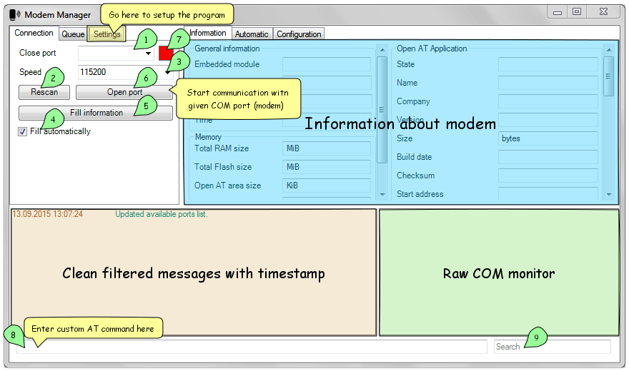
At start, all ports available within OS should be updated and filled in ports list 1. You can manually refresh them after inserting new devices by clicking “Rescan” 2 button.
After choosing needed port, select (or input manually) serial port speed (baud rate) for given device 3. Check or uncheck “Fill automatically” 4 checkbox: if it is checked, all information about modem will be filled automatically after you have connected to modem. You can also fill information manually using “Fill information” 5 button. The same result could be achieved by using F5 key (refresh information, see Keyboard shortcuts).
Click “Open port” 6 button to start communication. If port has been successfully opened, status indicator 7 will turn green. This status indicator could be 3 different colors: red for closed, green for opened, blue for “downloading mode”.
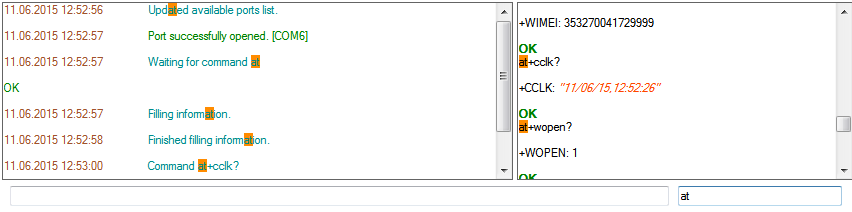
There’s console view at the bottom of the window. Left view is for pretty status messages and filtered AT-command results, where right view is raw COM (serial) monitor which displays all that flows through COM connection.
Text field 8 at the bottom allows to send AT commands explicitly into modem and text field “Search” 9 allows to search through both console windows.
Note
Search does not work incrementally: it just highlights all found matches so you can see them distinctly.
Using queue
Whether you are using console input or automatized button which processes number of tasks, these tasks will be added into the queue of commands which you can see, pause and resume. Also you can repeat last sent (unsuccessful) command.
Note
If you have “Autofocus queue” enabled in settings, this tab will be automatically opened when automatized sequence of commands is triggered (see ModemManager settings).
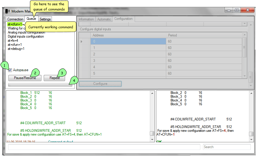
Here you can see list of commands that appeared after starting modem application configuration (see Application configuration). Currently working command is highlighted by green color if it is AT-command and by blue color if it is a process which uses progressbar below (XModem uploading, analog/digital inputs configuration).
Checkbox “Autopause” 1 makes sure that if an error occurs when command is executed, whole queue would be paused and you will be notified of that. In most cases, this checkbox should be enabled.
Button “Pause/Resume” 2 allows to manually pause/resume queue. If the queue is paused, you can still input new AT commands which will be immediately executed in second (parallel) queue which is always working in non-pausing mode for this case specially.
Button “Repeat” 3 allows to repeat last (failed) AT-command if the queue is currently paused. This command is executed in second queue, so this is just an automation around typing the same command again and again.
Progressbar 4 is needed for indicating progress of long events (such as downloading firmware or configuring lots of ports).
ModemManager settings
For more comfortable look and feel you may wish to setup it for your demands. To do so, go to “Settings” 1 tab. If you wish to skip settings chapter, go to Preparation section.
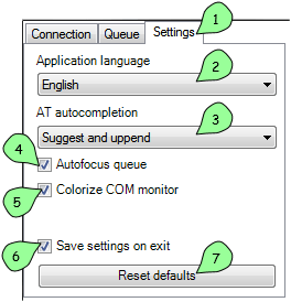
In listbox “Application language” 2 you can choose whole application language between two languages (currently): english and russian. This localizes not only user interface, but also various status messages in console view.
In listbox “AT autocompletion” 3 you can select autocompletion type for manual AT-command input from 4 different types:
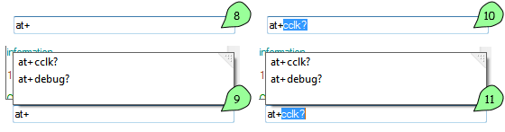
8 - None
9 - Suggest
10 - Append
11 - Suggest and append
Note
Autocompletion uses history of used AT-commands. There’s no predefined list of commands.
Checkbox “Autofocus queue” 4 does exactly what it promises to do: it focuses “Queue” tab (see Using queue) when automatized queue of commands is started, so that you can see whole queue coming and going.
“Colorize COM monitor” 5 checkbox improves look and feel of raw COM monitor at the bottom right side of application. It actually colorized input based on some rules, like orange for “quoted text”.
Checkbox “Save settings on exit” 6 is needed for saving settings and state of the application between sessions. If you want to start from current setup all the time, just uncheck this checkbox and if you change any settings, they will not remain after restart.
Warning
The program will not save “Save settings on exit” option if it is unchecked. To explicitely save it you should use Ctrl + S shortcut to manually save current settings (see Keyboard shortcuts).
And finally, button “Reset defaults” 7 resets all configurations to its default values without possibility to return :)
Preparation
Before using modem, you need to prepare it for work. If you obtained clean modem just from shop without our application and configuration, you need to write initial operational (OS) firmware and bootloader for it. To do this, click “Prepare empty modem” button at the lower left of the “Connection” tab. This should perform initial preparation on modem, so that you could use it properly.
Warning
You should run application from the installed folder with “Firmware” component installed, so that OS Firmware and Bootloader files (Firmware.dwl and Bootloader.dwl) is present within “Firmware” folder in the same directory where the application is located.
This step totally rewrites OS firmware and resets default modem configuration. To reconfigure modem for your needs, do the following on the “Automatic” tab:
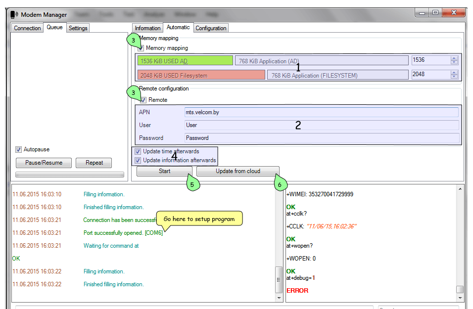
1 Remap Application & Filesystem disk space (if you need it).
2 Configure external (internet) APN for your simcard.
3 Make sure needed checkboxes is checked.
4 Check these if you want to update in-modem time and then refill information from modem.
5 Finally click the “Start” button to get started. Then the queue (see Using queue) will be filled with needed commands and modem will proceed to setup.
If you want to update firmware (or to download it the first time), click the “Update from cloud” 6 button. The process of updating application from the cloud is tricky though, because you will probably run into errors and will need debug skills to proceed. If you encounter any errors, please proceed to Troubleshooting area before contacting us.
Application configuration
Configuring application only works if you have our application inside your modem (which is obvious).
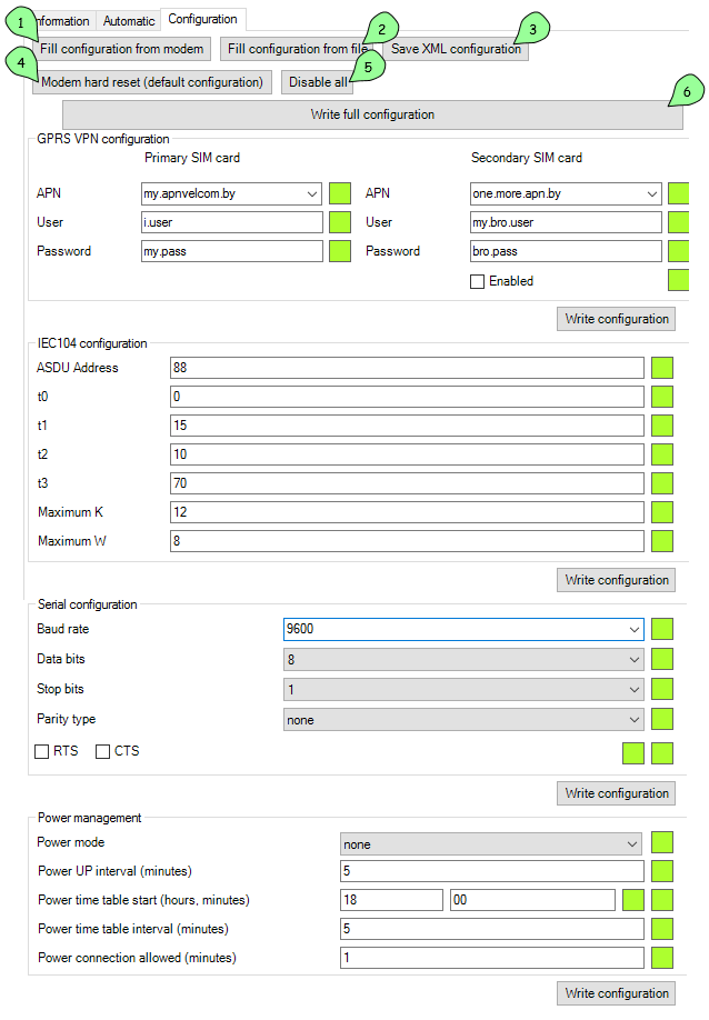
1 button fills information from modem.
2 button fills information from XML config file. You can get such file with predefined settings and just load whole configuration from it.
3 button saves current on-screen configuration into XML file for future use.
4 button resets default configuration which is defined by the version of application you are using.
5 button toggles all blocks for configuration. You can toggle single block by clicking on it while holding CTRL key.
6 button configures all on-screen configuration into modem.
Reference manual
| GPRS VPN Configuration | |
|---|---|
| Primary SIM card | |
| APN | Setup Access Point Name for primary SIM card |
| User | Setup APN User for primary SIM card |
| Password | Setup APN Password for primary SIM card |
| Secondary SIM card | |
| APN | Setup Access Point Name for secondary SIM card |
| User | Setup APN User for secondary SIM card |
| Password | Setup APN Password for secondary SIM card |
| Enable | Check Box, allows secondary SIM card usage |
| IEC104 configuration | |
|---|---|
| ASDU Address | Application Service Data Unit address. Denotes separate segments and their addresses inside a device |
| t0 | Reserved |
| t1 | Time to wait for acknowledge (“ACK”) to a transmitted APDU. If this time expires, the master assumes data has been lost and attempts to retransmit. The default settings is 15 s. |
| t2 | Time to wait before sending a supervisory APDU ACK. Increasing this setting can reduce bandwidth required for acknowledging. The default settings is 10 ms. |
| t3 | Idle time before sending TEST APDU. This is used by a 104 device to detect device connectivity. The default settings is 20 s. |
| Maximum K | Maximum unacknowledged transmitted APDUs. The master does not send more APDUs if the maximum number of ADPUs have been transmitted and have not been acknowledged. The default settings is 12. |
| Maximum W | Maximum unacknowledged received APDUs. This setting works in conjunction with T2 to limit how often the master acknowledges APDUs. Increasing this setting can reduce bandwidth required for acknowledging. The default settings is 8. |
| Serial Configuration | |
|---|---|
| Baud Rate | Setup Port Speed |
| Data Bits | Dropdown menu, sets Serial Frame Data Length |
| Stop Bits | Dropdown menu, sets Serial Frame Stop Bits |
| Parity Type | Dropdown menu, sets Serial Frame Parity Type |
| RTS | Check Box, sets usage of RTS serial flow control signal |
| CTS | Check Box, sets usage of CTS serial flow control signal |
| Power management | |
|---|---|
| Power mode | Dropdown menu, sets power management mode - none - no power management used. - sleep - simple power management algorithm: power up - measure - transfer data if possible - power down - timetable - complex power management algorithm: calculate time table of data transfer permitted periods, independent power-ups with measure cycle, data transferring only at allowed intervals |
| Power up interval (minutes) | Used in sleep and timetable modes, sets power up intervals. |
| Power time table start (hours, minutes) | Used in timetable mode, sets start time of calculated timetable, input in two fields if 24h format. |
| Power time table interval (minutes) | Used in timetable mode, sets interval between data transfer allowed windows. |
| Power connection allowed (minutes) | Used in timetable mode, sets length of data transfer allowed windows. |
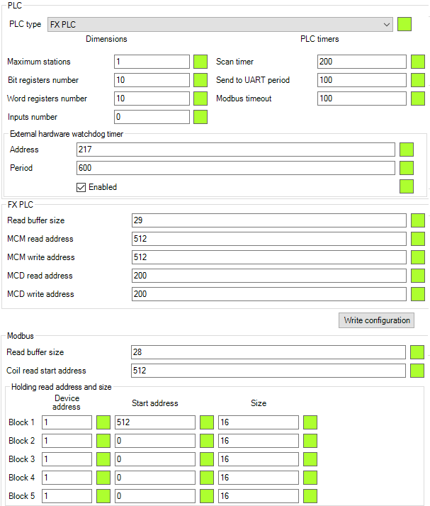
| PLC | |
|---|---|
| PLC Type | Drop menu, sets data source device type - SetPoint - connected 4..20 mA analog sensor. - Alpha PLC - connected with alpha-series PLC module. - FX PLC - connected with FX2 of FX3 series PLC module - modbus - connected with connected to modbus network as master Choosing options opens appropriate configuration sections below. |
| PLC timers | |
| Scan timer | Sets Data Polling period, in 0.1s units |
| Send to UART period | Sets delay Between Serial Data Requests, in 0.02s units |
| Dimensions | |
| Maxnum stations | Sets number of PLC devices in network. 1 for FX PLC, 1 or 2 for Alpha PLC. Ignored in SetPoint and Modbus modes. |
| Bit Registers number | Set number of Bits, read from single FX PLC or every Alpha PLC Ignored in SetPoint and Modbus modes. |
| Word Registers number | Set number of WORD registers, read from FX PLC or every Alpha PLC Ignored in SetPoint and Modbus modes. |
| External hardware watchdog timer | |
| Address | Setup address of special watchdog counter PLC register. Will be set as 0 every Period. Ignored in SetPoint mode. |
| Period | Setup External Hardware Watchdog reset period. Set’s in second units. |
| Enabled | Check Box, setups usage of External Hardware Watchdog mechanism. |
| FX PLC | |
|---|---|
| Read Buffer Size | Setup quantity of data units, read per request. Default value is 28 |
| MCM read address | M-registers (BIT) block start read address. Number stored in Bit Registers number option |
| MCM write address | M-registers (BIT) block start write address. Number stored in Bit Registers number option |
| MCD read address | D-registers (WORD) block start read address. Number stored in Word Registers number option |
| MCD write address | D-registers (WORD) block start write address. Number stored in Word Registers number option |
| Modbus | |
|---|---|
| Read buffer size | Configure quantity of data units per request. Deprecated. |
| Coil Read Start Address | Configure start address for COIL registers in modbus device #1. Quantity pf COILS is stored in Bit Registers number option |
| Holding Read Address and Size | |
| Block 1 .. 5 | Rows describes parameters for 5 modbus requests for periodic polling of HOLDING registers. |
| Device Address | Setups modbus network device address. |
| Start Address | Setups Start HOLDING register in data block. |
| Size | Setups Holding registers quantity. If 0 - this request will be ignored. |
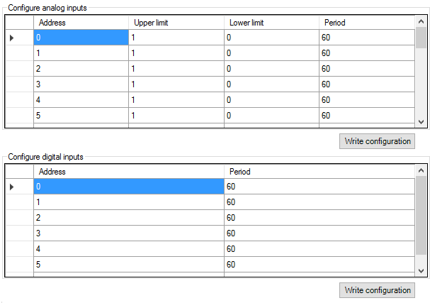
| Configure Analog Inputs | |
|---|---|
| Address | Analog (WORD) register index number. |
| Upper limit | Event generation control value. If current and previous register values difference will be more than this limit, event will be generated. Using for detecting unexpected fast changes of register value. Default value is 1. |
| Lower limit | Event generation control value. If current and previous register values difference will be less, than this limit, even if Time event occurs, event will not be generated. Using for noise reduction. Default value is 0. |
| Period | Event generation control value. Time out from last generated event. If it expires, new event will be generated. Default value is 60 seconds. |
| Configure Digital Inputs | |
|---|---|
| Address | Bit (BIT) register index number. |
| Period | Event generation control value. Time out from last generated event. If it expires, new event will be generated. |
Troubleshooting
Error occurs when trying updating from cloud
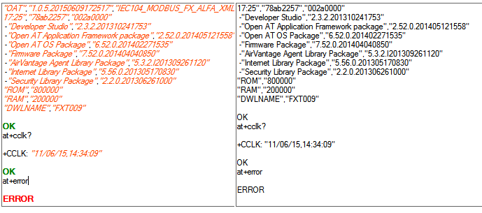
If error occurred before at+wdss=1,1 command is executed, it most likely happened because you have no SIM card installed. Please, check that you have SIM card installed and that your modem have reliable internet connection (correct APN is set).
Also, make sure that your modem is patched (see Preparation). You should click “Prepare empty modem” at least once per each new modem.
Program stopped working and port has disappeared
This is presumably Sierra Wireless USB driver problem. You will most likely need to reboot your PC to be able to see port again.
If this error happened when you already set up configuration in the “Configuration” tab, you can simply save whole configuration into XML file, restart application and load this configuration from XML file.